
Introduction
Concurrently with our seventh game project at The Game Assembly, we had the opportunity to specialize; to plan an independent foray into a subject which we wanted to explore further.
For my specialization I chose to try and implement volumetric lighting in our custom game engine. My main goal was to implement a volumetric directional light, and to optimize it best I could. Would there be time left, my secondary goal was to extend this implementation to point lights, spot lights and what I called “box” lights.
We had five weeks half-time to do this, as well as setting up our personal portfolio. I planned for letting my secondary goal slide, and to focus on my main goal.
I based my implementation on a talk at Digital Dragons by Benjamin Glatzel for Deck 13’s Lords of The Fallen.
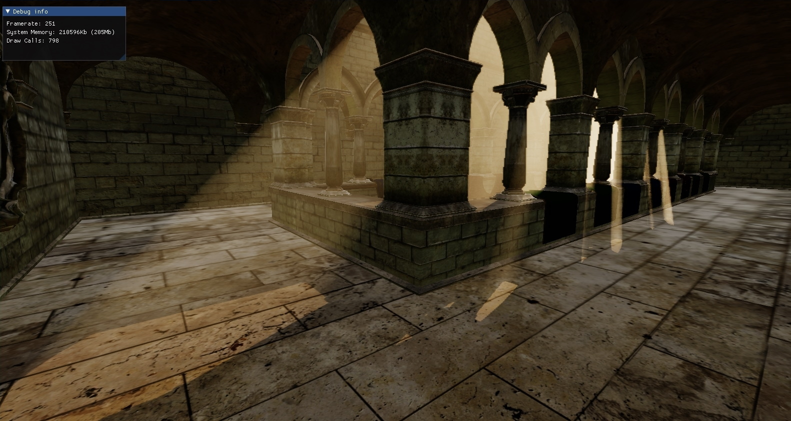
After loading the Crytek Sponza scene using our model loading pipeline, I set out to create a first working version of a volumetric directional light. Shadowmapping was ready for the directional light so I started with ray marching in the fragment shader of a separate light pass.
Implementation
The current fragment’s world position is extracted from the depth map. Then the world space camera position and fragment position are transformed into light view space and the ray marching direction is calculated from these. An upper limit on the ray marched distance is set using this difference prior to normalization, and the size of each ray marching step is determined using a tweakable number of samples.
View Code
PixelOutput main(VertexToPixel input)
{
    PixelOutput output;

    float raymarchDistanceLimit = 999.0f;

    float3 worldPosition = PixelShader_WorldPosition(input.myUV).rgb;
    float3 camPosition = cameraPosition.xyz;

    worldPosition -= directionalLightPosition.xyz;
    float3 positionLightVS = mul(toDirectionalLightView, worldPosition);

    camPosition -= directionalLightPosition.xyz;
    float3 cameraPositionLightVS = mul(toDirectionalLightView, camPosition);

    float4 invViewDirLightVS = float4(normalize(cameraPositionLightVS.xyz - positionLightVS.xyz), 0.0f);
    float raymarchDistance = clamp(length(cameraPositionLightVS.xyz - positionLightVS.xyz), 0.0f, raymarchDistanceLimit);

    float stepSize = raymarchDistance * numberOfSamplesReciprocal;

    float3 rayPositionLightVS = positionLightVS.xyz;

    // The total light contribution accumulated along the ray
    float3 VLI = 0.0f;

    [loop]
    for (float l = raymarchDistance; l > stepSize; l -= stepSize)
    {
        ExecuteRaymarching(rayPositionLightVS, invViewDirLightVS.xyz, stepSize, l, VLI);
    }

    output.myColor.rgb = directionalLightColor.rgb * VLI;
    output.myColor.a = 1.0f;
    return output;
}
In the ExecuteRaymarching function, the ray position is incremented towards the camera position and the accumulated light contribution is calculated using the in-scattering term of the
Radiative Transfer Equation, ignoring multiple scattering.
In the directional light case, there is no world space attenuation calculated here, but the source power of the light and the scattering probability can be tweaked outside of the shader.
View Code
void ExecuteRaymarching(inout float3 rayPositionLightVS, float3 invViewDirLightVS, float stepSize, float l, inout float3 VLI)
{
    rayPositionLightVS.xyz += stepSize * invViewDirLightVS.xyz;

    float3 visibilityTerm = ShadowFactor(rayPositionLightVS.xyz).xxx;

    // Distance to the current position on the ray in light view space
    float d = length(rayPositionLightVS.xyz);
    float dRcp = rcp(d); // reciprocal

    float3 intensity = scatteringProbability
        * (visibilityTerm * (lightPower * 0.25 * PI_RCP) * dRcp * dRcp)
        * exp(-d * scatteringProbability)
        * exp(-l * scatteringProbability)
        * stepSize;

    VLI += intensity;
}
Without any optimizations, this render pass is prohibitively expensive, requiring between 64 and 128 samples per fragment on a full resolution target to look serviceable.
Optimization
The two primary optimizations I implemented were rendering volumetrics to a half-resolution accumulation buffer, and interleaved sampling (see Glatzel slide 42). Rendering to a half-resolution target meant having to blur the accumulation buffer in order to hide the fact. Together with interleaved sampling, the number of samples required per fragment was minimized to the point that performance increased in the end, however.
Before executing the ray marching, an offset to the starting position is calculated based on an 8 by 8 grid and the number of samples is reduced, taking advantage of the fact that the intensity differs by small amounts between neighboring fragments. This reduces the number of necessary samples to as low as 16 samples.
View Code
PixelOutput main(VertexToPixel input)
{
    [...]

    float stepSize = raymarchDistance * numberOfSamplesReciprocal;

    // Input position offset by 0.5f from center of fragment
    float2 interleavedPosition = fmod(input.myPosition.xy - 0.5f, INTERLEAVED_GRID_SIZE);

    float index = (floor(interleavedPosition.y) * INTERLEAVED_GRID_SIZE + floor(interleavedPosition.x));

    // lightVolumetricRandomRayIndices contains the values 0..63 in a randomized order
    float rayStartOffset = lightVolumetricRandomRayIndices[index] * (stepSize * INTERLEAVED_GRID_SIZE_SQR_RCP);

    float3 rayPositionLightVS = rayStartOffset * invViewDirLightVS.xyz + positionLightVS.xyz;

    float3 VLI = 0.0f;

    [loop]
    for (float l = raymarchDistance; l > 2.0f * stepSize; l -= stepSize)
    {
        ExecuteRaymarching(rayPositionLightVS, invViewDirLightVS.xyz, stepSize, l, VLI);
    }

    [...]
}
After rendering to the accumulation buffer a bilateral Gaussian blur is applied, separated in horizontal and vertical passes. The advantage of a bilateral blur is that it is edge preserving, contrary to a regular Gaussian blur.
The bilateral passes will smear the inside of the light volumes while preserving the edges.
View Code
// Horizontal
PixelOutput main(VertexToPixel input)
{
    PixelOutput returnValue;

    float texelSize = 1.0f / (myResolution.x / 8.0f);
    float3 blurColor = float3(0.0f, 0.0f, 0.0f);
    float normalizationFactor = 0.0f;
    float bZ = 1.0 / normpdf(0.0, SIGMA);
    float colorFactor = 0.0f;
    float3 originalPixelValue = fullscreenTexture1.Sample(defaultSampler, input.myUV.xy).rgb;

    unsigned int kernelSize = 5;
    float start = (((float) (kernelSize) - 1.0f) / 2.0f) * -1.0f;

    for (unsigned int i = 0; i < kernelSize; i++)
    {
        float2 uv = input.myUV.xy + float2(texelSize * (start + (float) i), 0.0f);
        float3 resource = fullscreenTexture1.Sample(defaultSampler, uv).rgb;
        colorFactor = normpdf3(resource - originalPixelValue, SIGMA) * bZ * gaussianKernel5[i];
        normalizationFactor += colorFactor;
        blurColor += resource * colorFactor;
    }

    returnValue.myColor.rgb = blurColor / normalizationFactor;
    returnValue.myColor.a = 1.0f;
    return returnValue;
};
If the colorFactor variable is not weighted by an appropriate measure (such as depth) the result may look noisy or pixelated around the edges of the volume, especially for hard-to-define fading edges where attenuation takes place. This is not done above, as I could not produce satisfying results.
Honorable Mentions
Having a fairly quick initial setup, I tried accomplishing my secondary goal prior to optimizing. Point lights were implemented but had utilized no shadowmapping, so I started with ray marching from the point lights and created two other light types from scratch hoping I would have the time to realize shadow mapping for all of them.
The other two light types were spot lights and what I called “box” lights. Box because they differ from the usual rectangle or area lights in that they have no angular falloff at the edges, essentially working as localized directional lights.
All the lights were provided geometry; a cube for point lights, a pyramid shape for spots and a cuboid for the box lights. They all functioned as light sources, but while I solved the actual volumetrics for box and point lights, I ran out of time before I could accurately provide shadow mapping for either of them. This meant the visibility function could not be evaluated, rendering them virtually unusable for volumetric lighting.
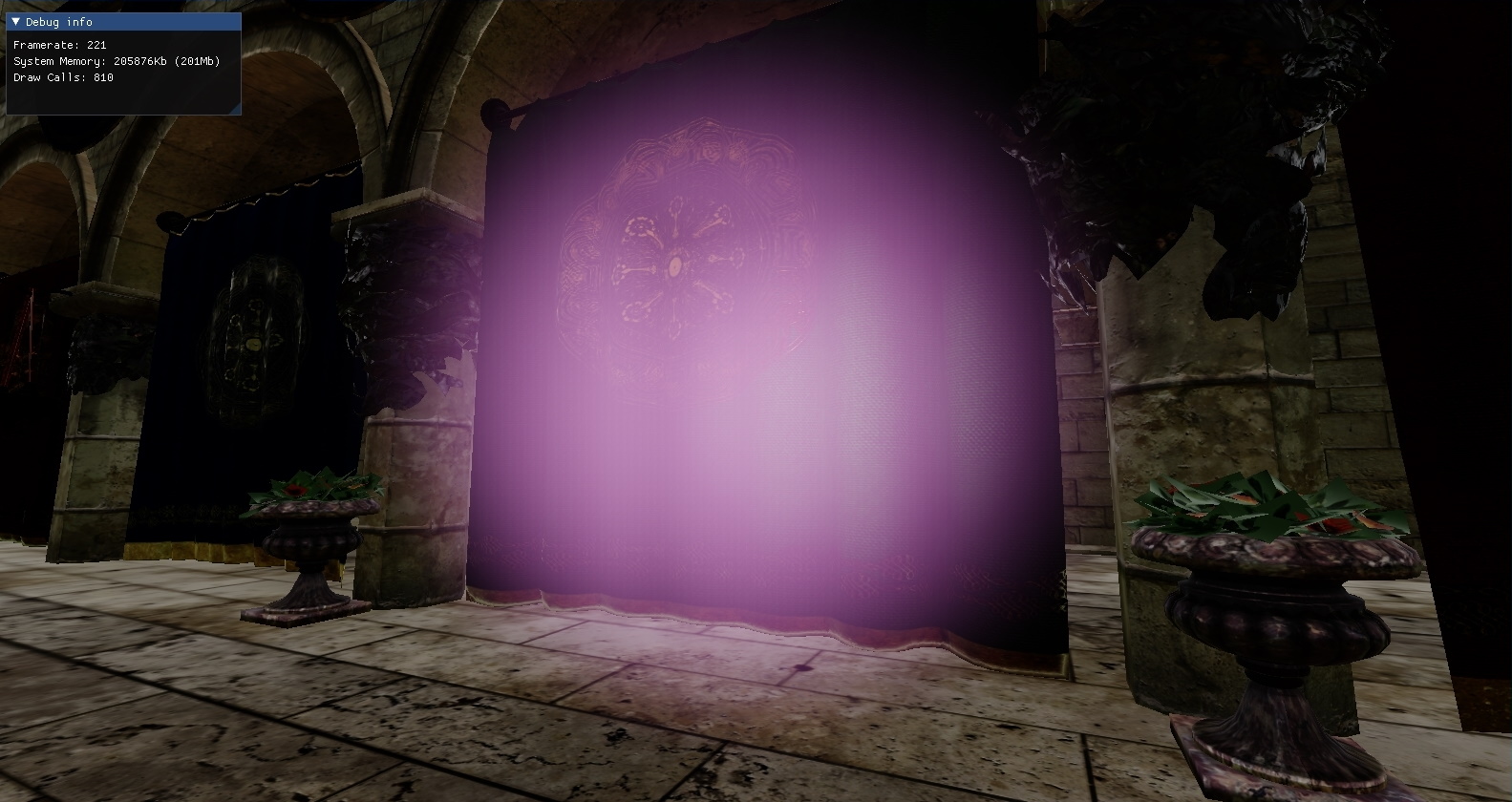
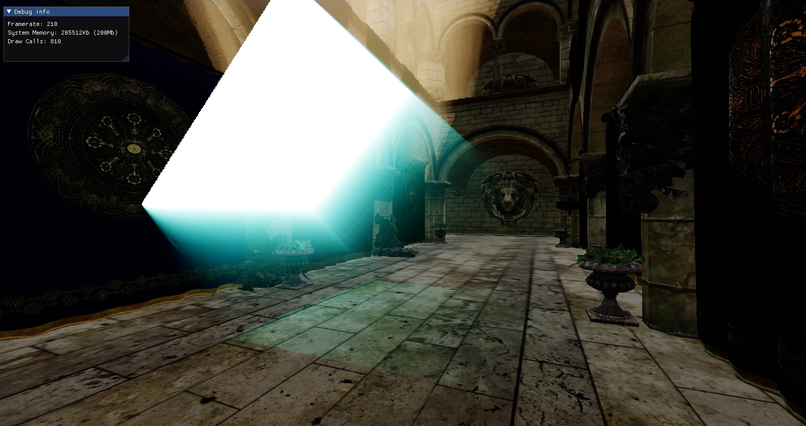
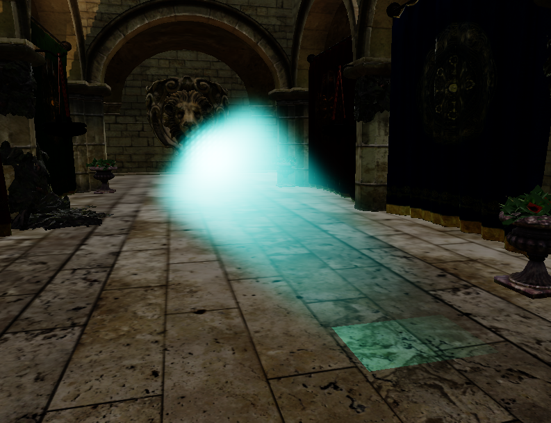
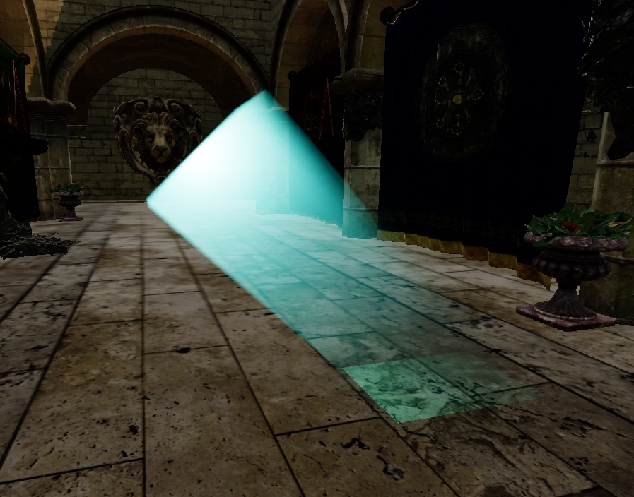
I did explore different phase functions however, using the Henyey-Greenstein phase function as the default on the box light, with a tweakable g-value (g = 0, isotropic scattering above).
Note the noisy edges of the directional light in the right picture above, as well as at the ends of the box light itself.
Reflections
All in all I am satisfied in reaching my primary goal, which was to implement a volumetric directional light and to try and optimize it best I could.
I would not underestimate the time needed to create the other light types from scratch again though. I found myself working on the basic lighting of the box light and spot light more than I expected, and if given the choice again I would have focused on optimizing for the directional light prior to working with new light types.
I ventured to try out all the steps of the optimization outlined by Glatzel, including “nearest depth up-sampling” (see slide 38), to further make up for the fact that we are rendering to a half-resolution target. I could not make this work to satisfaction, but it would be greatly beneficial in making the volumetric directional light look good I believe.